|
Tipo Type Typ |
Dimensioni – Dimensions– Abmessungen(mm) |
Peso Weight |
CSL (kg) |
CSR (kg)
|
||||||||||||||
|
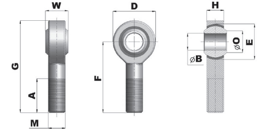
B
|
W
|
H
|
O
|
D
|
F
|
G
|
A
|
E
|
M
|
|||||||||
|
Gewicht |
Rad |
Ass |
||||||||||||||||
|
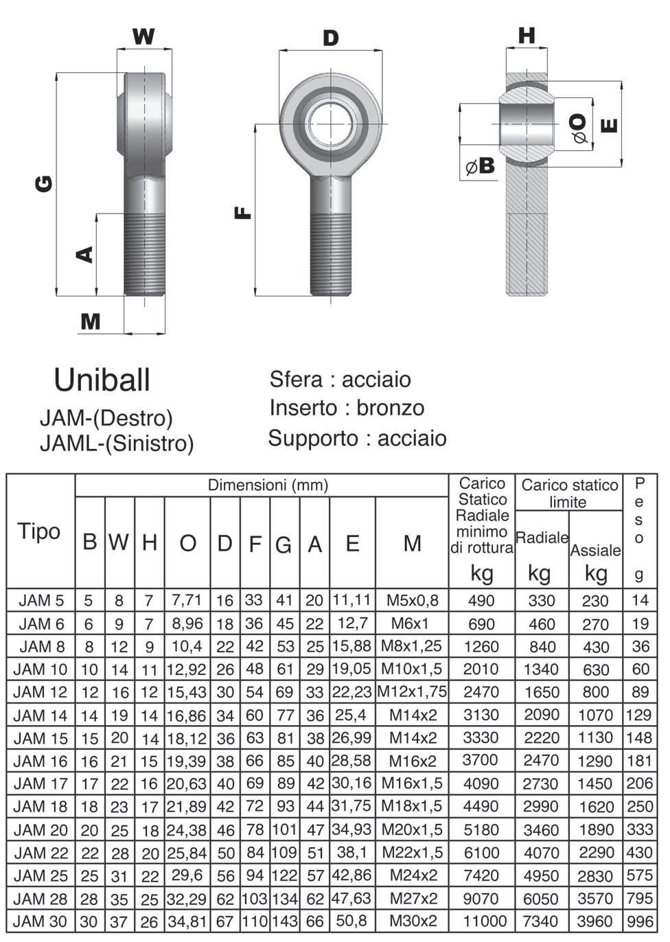
JAM 5 |
5 |
8 |
7 |
7,71 |
16 |
33 |
41 |
20 |
11,11 |
M5x0,8 |
14 g |
330 |
230 |
490 |
||||
|
JAM 6 |
6 |
9 |
7 |
8,96 |
18 |
36 |
45 |
22 |
12,70 |
M6x1 |
19 g |
460 |
270 |
690 |
||||
|
JAM 8 |
8 |
12 |
9 |
10,40 |
22 |
42 |
53 |
25 |
15,88 |
M8x1,25 |
36 g |
840 |
430 |
1260 |
||||
|
JAM 10 |
10 |
14 |
11 |
12,92 |
26 |
48 |
63 |
29 |
19,05 |
M10x1,5 |
60 g |
1340 |
630 |
2010 |
||||
|
JAM 12 |
12 |
16 |
12 |
15,43 |
30 |
54 |
69 |
33 |
22,23 |
M12x1,75 |
89 g |
1650 |
800 |
2470 |
||||
|
JAM 14 |
14 |
19 |
14 |
16,86 |
34 |
60 |
77 |
36 |
24,40 |
M14x2 |
129 g |
2090 |
1070 |
3130 |
||||
|
JAM 15 |
15 |
20 |
14 |
18,12 |
36 |
63 |
81 |
38 |
26,99 |
M14x2 |
148 g |
2220 |
1130 |
3330 |
||||
|
JAM 16 |
16 |
21 |
15 |
19,39 |
28 |
66 |
85 |
40 |
28,58 |
M16x2 |
181 g |
2470 |
1290 |
3700 |
||||
|
JAM 17 |
17 |
22 |
16 |
20,63 |
40 |
69 |
89 |
42 |
30,16 |
M16x1,5 |
206 g |
2730 |
1450 |
4090 |
||||
|
JAM 18 |
18 |
23 |
17 |
21,89 |
42 |
72 |
93 |
44 |
21,75 |
M18x1,5 |
250 g |
2990 |
1620 |
4490 |
||||
|
JAM 20 |
20 |
25 |
18 |
24,38 |
46 |
78 |
101 |
47 |
34,93 |
M20x1,5 |
333 g |
3460 |
1890 |
5180 |
||||
|
JAM 22 |
22 |
28 |
20 |
25,84 |
50 |
84 |
109 |
51 |
38,10 |
M22x1,5 |
430 g |
4070 |
2290 |
6100 |
||||
|
JAM 25 |
25 |
31 |
22 |
29,60 |
56 |
94 |
122 |
57 |
42,86 |
M24x2 |
575 g |
4950 |
2830 |
7420 |
||||
|
JAM 28 |
28 |
35 |
25 |
32,29 |
62 |
103 |
134 |
62 |
47,63 |
M27x2 |
795 g |
6050 |
3570 |
9070 |
||||
|
JAM 30 |
30 |
37 |
26 |
34,81 |
67 |
110 |
143 |
66 |
50,80 |
M30x2 |
996 g |
7340 |
3960 |
11000 |
||||
|
CSL
|
Carico statico limite (Radiale/Assiale) Static limit load (Radial/Axial) Statische Grenzlast (Radial/Axial) |
CSR
|
Carico statico radiale minimo di rottura Minimum radial static breaking load Minimale radiale statische Bruchlast |
|||||||||||||||
![]() Zur Vergrößerung auf das Bild klicken
Zur Vergrößerung auf das Bild klicken


| Kugel / Halterung | Stahl |
| Einsatz | Bronze |
| Uniball JAM | Rechts |
| Uniball JAML | Links |
General precautions to be followed in the installation and assembly of load cells: