GICAM verkauft verschiedene Arten von Signalwandler. Wir haben Signalwandler, die serielle Protokolle durch Funkfrequenzen übertragen, sehr einfach zu programmieren und zu steuern. Unsere Konverter sind für den Einsatz in der Industrie geeignet. Wir bieten Signalwandler an, die analoge Eingangssignale in standardisierte analoge Signale umwandeln und Signalwandler, die an Geräte mit RS-485- oder RS-422-Protokollen angeschlossen werden können.
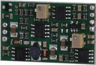
4 – 20 mA WANDLER
![]() Zur Vergrößerung auf das Bild klicken
Zur Vergrößerung auf das Bild klicken

| Stromversorgung Karte | 12-30 V Gleichstrom | |
| Stromversorgung Zelle | 4 V Gleichstrom pro Zelle (1 Zelle mit 350 Ω oder 700 Ω) gegen Kurzschluss geschützt | |
| Stromaufnahme | 0,6 W mit Wägezelle da 350 Ω | |
| Ausgang | 4 mA ÷ 20 mA (carico <=250W) | |
| Eingangssempfindlichkeit | 1 – 2 mV / V abhängig vom Widerstand R3 (15 ppm): 1mV/V mit R3 = 200 Ω, 2 mV / V ohne R3 | |
| Abmessungen | 35 x 22 x 8 mm | |
| Anschlüsse | Lötdrähte | |
| Zellenanschluss | Mit 4 Drähten | |
| Lagerstemperatur | - 10 °C / + 50 °C (14 °F / 122 °F) | |
| Betriebstemperatur | - 20 °C / + 60 °C (- 4 °F / 140 °F) | |
| Linearität | 0.02% | |
| Temperaturstabilität | 30 ppm/°C | |
| Nullpunkteinstellung | ± 10 % des Skalenendwertes durch Multiturn-Potentiometer | |
| Gain-Einstellung | ± 10 % des Skalenendwertes durch Multiturn-Potentiometer | |
| Analogfilter | 50 Hz | |
| Schutz vor fehlerhaften Anschlüssen | Verpolungsschutz der Stromversorgung, Kurzschlussschutz am mA-Signal | |
| Typ | Verbinder J1+J2 S138 |
| Länge | ND |
| 1 | + Exc. Load cell |
| 2 | + Signal load cell |
| 3 | - Signal load cell |
| 4 | - Exc. Load cell |
| 5 | + Power Supply 12 - 30 Vcc |
| 6 | - Power Supply |
| 7 | Output 4 - 20 mA (the output GND is power pin 6) |
General precautions to be followed in the installation and assembly of load cells: