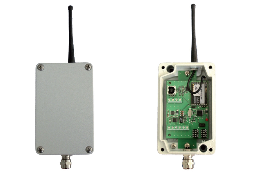
SCHNITTSTELLE von RS232 / RS485 / USB zu HF.
Wahl der gewünschten Konfiguration (MULTI oder SINGLE) über Hardware-Brücke.
In der MULTI-Konfiguration können bis zu 15 Sendegeräte TRF an denselben Funkkanal angeschlossen werden.
Wahl des RF-Kanals, Baudrate und Kommunikationsadresse durch DIP-SCHALTER, Speisung 4.5Vdc-15 Vdc XX oder über USB-Anschluss. PC-Anwendung für Konfiguration.
Bedienungsanleitung herunterladen ![]()
![]() Zur Vergrößerung auf das Bild klicken
Zur Vergrößerung auf das Bild klicken

| Stromversorgung | 4,5-15 V Gleichstrom, 50 mA | |
| Betriebstemperatur | -10 / +50 °C (14 / 122 °F) Maximal 85% nicht kondensierend | |
| Lagertemperatur | -20 / +60°C (-4 / +140°F) | |
| Außenmaße | 126 x 79 x 41 mm / 4.96 x 3.11 x 1.61 in (l x h x p) ohne Antenne und Stecker | |
| Gehäusematerial | Aluminium-Druckguss | |
| Schutzklasse | IP 65 | |
| Anschlüsse | Schraubklemmen mit 5,08 mm Rastermaß und Kabelverschraubung | |
| Rs232 | Kommunikationsparameter: 9600/19200/38400,N,8,1. Segnali gestiti: Txd, Rxd, Sgnd. | |
| Rs422/Rs485 | Kommunikationsparameter: 9600/19200/38400,N,8,1. | |
| USB | Kommunikationsparameter: 9600/19200/38400, N, 8, 1. Verwaltete Signale: Txd, Rxd, Sgnd | |
| Frequenz | 866-868 MHz | |
| Anzahl RF-Kanäle | 7 wählbar über DIP Schalter | |
| Anzahl Netzwerkadressen | 15 wählbar über DIP Schalter | |
| Durchschnittliche Reichweite | 50 m (165 feet) | |
| Normkonform | EN 300 220, EN 301 489, EN 60950, EN61000-6-2, EN61000-6-3, EN61010-1 | |
General precautions to be followed in the installation and assembly of load cells: